🔁 Op-Amp Basics: Inverting and Non-Inverting Amplifiers
Now that you understand the ideal op-amp concept, let’s look at the two most fundamental op-amp configurations:
- Non-Inverting Amplifier
- Inverting Amplifier
Almost every op-amp circuit you’ll ever design is built from these two ideas.
➕ Non-Inverting Amplifier
This is the most intuitive op-amp configuration.
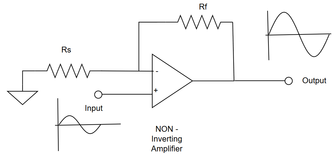
🔌 Configuration
- Input signal → Non-inverting input (+)
- Feedback → From output to inverting input (−) using resistors
🔄 Behavior
- Input goes up → Output goes up
- Input goes down → Output goes down
The signal is not flipped.
📐 Gain Formula
Where:
- = feedback resistor (output → − input)
- = resistor from − input to ground
📊 Example
If:
Then:
So:
Very predictable and stable.
✅ Advantages
- Very high input impedance
- Does not load sensors
- No phase inversion
- Can be unity gain (buffer)
📌 Unity gain buffer:
➖ Inverting Amplifier
Here the signal is applied to the inverting input.
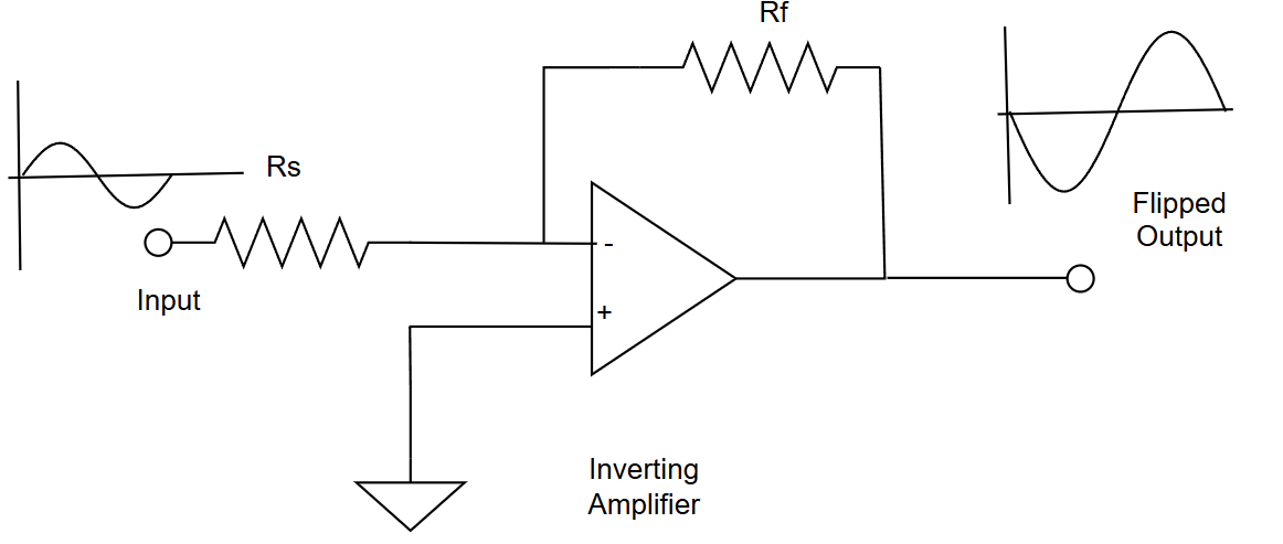
🔌 Configuration
- Input signal → Inverting input (−) through a resistor
- Non-inverting input (+) → Ground
- Feedback from output → − input
🔄 Behavior
- Input goes up → Output goes down
- Input goes down → Output goes up
The output is 180° out of phase (inverted).
📐 Gain Formula
Where:
- = input resistor
- = feedback resistor
The negative sign means inversion.
📊 Example
If:
Then:
So:
✅ Advantages
- Precise, stable gain
- Gain can be less than 1
- Easy to sum multiple inputs
- Defined input impedance ()
⚖️ Key Differences at a Glance
| Feature | Non-Inverting | Inverting |
|---|---|---|
| Phase | Same as input | Inverted (180°) |
| Input impedance | Very high | Set by resistor |
| Gain formula | ||
| Unity gain | Yes | Yes |
| Signal summing | Harder | Easy |
🔁 Feedback – The Secret Sauce
Both circuits rely on negative feedback.
Golden rule applies:
Feedback forces the op-amp to settle at a stable output instead of saturating.
Without feedback:
- Output slams to supply rails
- Circuit becomes a comparator
With feedback:
- Linear
- Predictable
- Stable
🧪 Practical Beginner Example (Non-Inverting)
Sensor output:
Required gain:
Choose:
Perfect for temperature, pressure, light sensors.
➕ Practical Example (Inverting)
Want to add signals:
Use:
- Multiple input resistors
- One feedback resistor
This is the foundation of summing amplifiers.
🚫 Common Beginner Misconception
“Inverting means something is wrong”
❌ False.
Inversion just means:
In audio, control systems, and signal processing, inversion is often intentional.
🧭 Choosing the Right One
Use Non-Inverting when:
- Sensor has high impedance
- Phase must be preserved
- You want a buffer or voltage follower
Use Inverting when:
- You need exact gain control
- You’re summing signals
- Input impedance must be known
- Phase inversion doesn’t matter
✅ The Bottom Line
- Non-inverting: signal stays upright, high input impedance
- Inverting: signal flips, precise gain control
- Both rely on negative feedback
- These two circuits form the foundation of all op-amp designs
Master these, and op-amps become predictable, powerful tools instead of mysterious black boxes.